
Analog Line Following Robot
Content by:- Achintha Rathnayake | Written by:- Samindra Kumari
A Line-following robot is the fundamental step in robotics for many robotics enthusiasts. It is also a simple task generally accomplished with basic knowledge of Arduino coding, Microcontrollers, and a PID algorithm. However, in this article, we discuss a line-following robot made entirely of analog components.
An Analog Line-following robot is a device that moves over a thick line with sharply contrasting colors, such as black lines on a white background. It does not contain a microcontroller. It is solely made of electronic components such as Op-Amps, Transistors, Diodes, Resistors, Potentiometers, and other analog electronic components.
Here, the sensor panel creates analog voltage differences. These voltage differences are identified by the Op-Amp which is in comparator configuration and output logic high or low. According to the logic output of the comparator, each motor is controlled independently through a motor driver.

In analog line follower, the sensor panel creates an analog voltage variation. This voltage variation is identified by the Op-Amp which is in comparator configuration and output logic high or low. Then that is applied to 2 motors through the motor driver. According to the logic output of the comparator, each motor is controlled independently.
Subparts
- IR Sensor
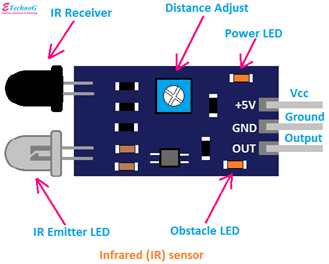 The emitter LED emits infrared radiation, which reflects at an object and the reflected rays are sensed by the IR sensor. As a result, IR sensors can recognize objects in front of them. In addition, the intensity of the incoming IR beam and the voltage output of the sensor can determine the color of the surface since white surfaces reflect more IR compared to black surfaces.

- Comparator (LM358)
 This is an Op-Amp IC that consists of two opAmps that can compare two voltages. It will power up the operational amplifiers. Pin 4 is the ground pin. When pin 3 voltage is higher than pin 2 voltage output of pin 1 becomes high and otherwise, it becomes low.
Below is the sub-circuit we can use with the comparator.
 Here, two outputs of IR sensors should connect to non-inverting pins of two Op-Amps, and inverting pins should be connected to potentiometer outputs to adjust the threshold voltage to identify black and white. Then outputs should output high when the IR sensor detects white and low when the sensor detects black.
- Motor Driver (L293D)
By this component, we can control motors. The number of motors that can be controlled depends on the configuration.
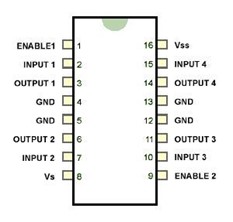
Two motors are connected to output pins (pin 3 – 6, pin 11-14). Pin 16 is the Vcc pin for this internal logic circuit so it should be connected to 5V. The voltage needed for motors is supplied using pin 8. It can be varied between 5-36 V s. Input pins are to control the direction of the motor rotates. Enable pins are the speed controllers. If the left side ‘enable pin’ is low, then the motor controlled by the left side of the IC is stationary. When we increase the voltage of the left side ‘enable pin’, the left side motor speed also increases.
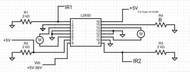
This is the diagram of the above-mentioned connections of the motor driver.
L293D is a motor driver IC. In L293 there are two versions;
- L293
- L293D
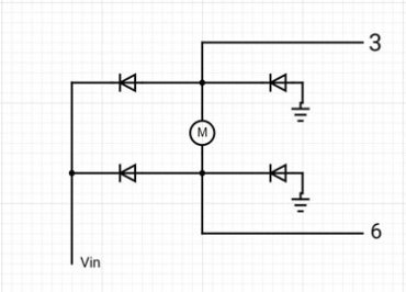
The difference between the two versions is, L293D has built-in diodes; D stands for diodes and L293D can handle a peak current of 1.2A while L293 can handle up to 2A. If you are using L293, then you should use external diodes.
Diodes must be chosen according to the current requirement. If you need to handle a maximum of 1A current, then you can use 1A diodes. But if you need full capacity, then use 2A diodes. Diodes should be used as follows.
- Power Supply
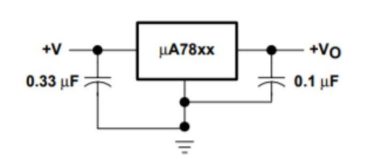
To provide power to the internal logic circuit of L293D and LM358 Circuit, you can use an LM7805 Voltage regulator IC. If your battery voltage does not exceed the maximum voltage of your motor, you can directly connect the positive terminal of the battery to pin 8 of L293D. If you need to lower the voltage to motors, you can use LM78XX IC according to voltage requirements. But LM78XX IC series can regulate a maximum of 1A. Consider the current constraint and use appropriate methods.
Method
First, we should set the threshold for the comparator. For that, we have to connect two LEDs for the outputs of the comparator and move a white paper in front of the IR sensor at about the distance between the transmitter and the floor when the robot is on the floor. Then adjust the potentiometer to the point where the motor begins to drive.
We can develop this robot to follow a black line on a white surface or to follow a white line on a black surface. But in both cases, we have to make sure that IR sensors are in the white color area, otherwise, if the motor driver enables pins to get logic low, motors will be stationary.
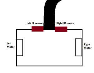
Assume an instance of a robot following a black line on a white surface. As IR rays are reflected by the white surface, motors are rotated. Then the robot comes to a bend to the right. As the right IR detects the black line, it will signal it by setting the signal line to logic low. Therefore, the right motor stops and the left motor is still spinning. Therefore, the robot will turn right.
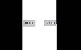
The white line follows, arrange IR LEDs as follows.
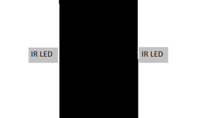
Blackline follows, arrange IR LEDs as follows.
Troubleshooting
- After completely soldering and assembling the robot, power it up & keep it on a white surface. If one or both motors spin in the reverse direction, you should invert the direction of rotation. This can be done by changing logic levels of pins 2 and 7 pairs and 15 and 10 pairs. But they are soldered and fixed. So just swap the wires of the motor.
- When you keep on track, if the robot is going in the opposite direction of the bend, just swap the signal lines from LM358. Just swap the wires connecting to pins 1 and 9 of L293D IC.